I’ve been stumped for a little while trying to decode LightwaveRF data using a cheap 433.92MHz receiver and a Arduino Nano.
Today I’ve finally cracked it! Thanks to Geek Grandad’s LightwaveRF GitHub repo I finally figured out the missing link - my zeros were not zeros, but instead 10s! Sure, this doesn’t make sense yet, but let me explain.
The setup
To capture the radio data, I used a cheap 433.92MHz receiver hooked up to an Arduino Nano. The wiring was simple: just wire up +5V and GND to the radio from the Arduino, and connect the DATA pin to Arduino Nano digital pin 2. I wrote a quick and dirty receive sketch and installed it to the Arduino. This sketch just listens for the “CHANGE” event on the radio’s pin (i.e. when it transitions from 0 to 1, or from 1 to 0) and then effectively times the duration it was in each state (high or low).
For example, if it was low for 250us (microseconds) then high for 350us then low for 250us, the sketch would output the equivalent of “250, 350, 250”. Each value was compressed down to 2 bytes and sent over the serial link to my python script, which would receive the data, decode it back to textual numbers, write it to a capture file and then plot a graph of it so I could check the data that was received made sense.
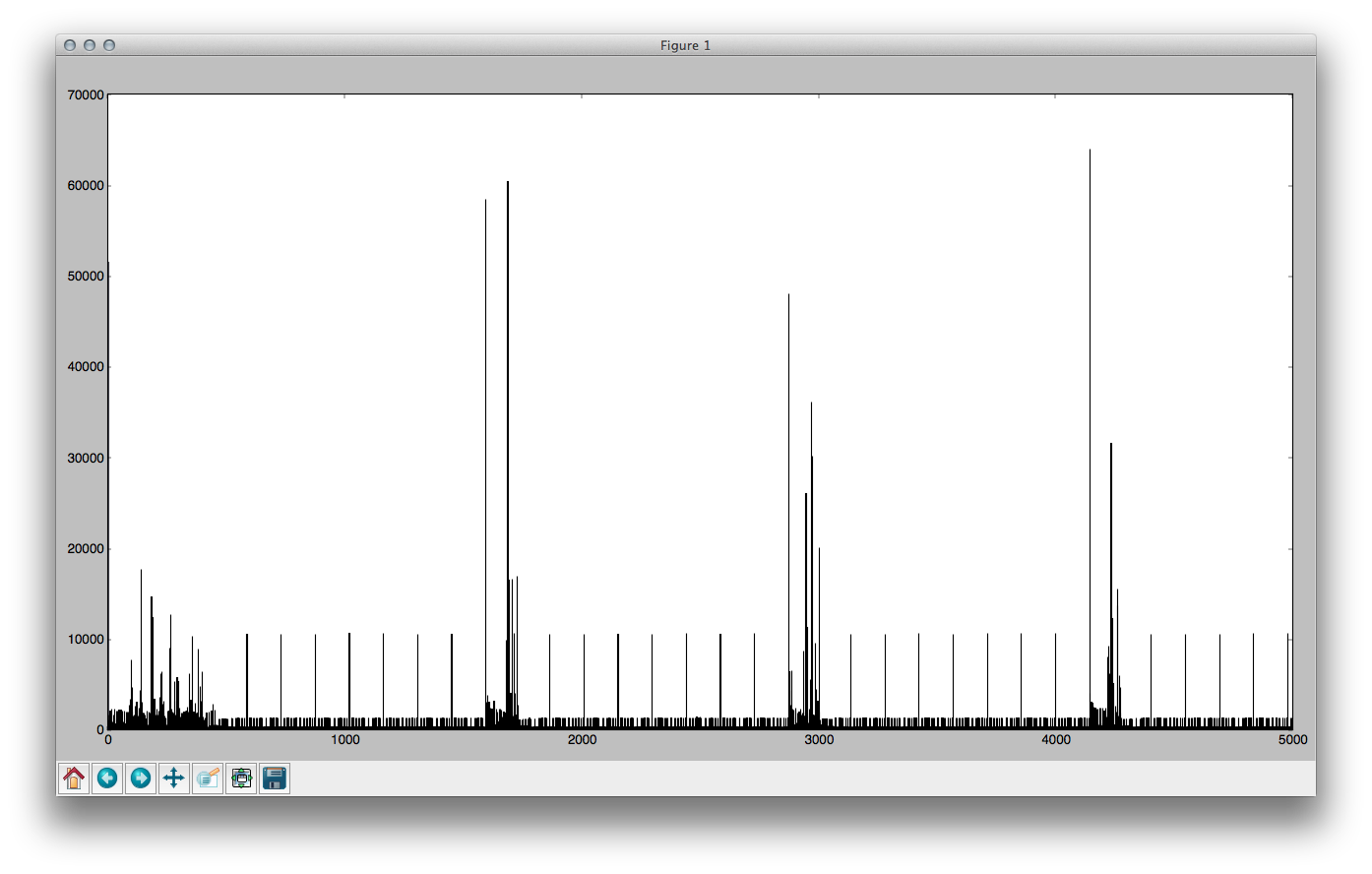
In the image above the regular bits is the sensible data (4 different button presses, each automatically repeated to help with collisions) and the areas in-between are just noise. The x-axis is the record number (from 0 through to 5000) and the y-axis is the value of that record - i.e. how long in microseconds the pin remained in one state before changing.
Limitations
Due to not wanting to overflow the ringbuffer in the Arduino sketch I only allowed each capture to go up to 5,000 records (which worked out to be pretty variable, but generally a couple of seconds).
Capture
I have a LightwaveRF remove that’s basically a matrix of on/off buttons. There are 4 sets of on/off buttons (8 buttons total), and then a slider switch that has 4 positions, which effectively means that there are 16 * 2 = 32 buttons. I captured each of these, both pressed and held.
I also have a “Mood Remote” which I captured separately.
Analysis
Having captured the data, I then went about trying to decode it. I noticed that every other record was of a similar duration, and the alternating records varied but took two forms - either long or short - I assumed therefore that this meant that they carried the data and as they came in 2 lengths I arbitrarily stated that the short length was a zero, and the long length was a 1.
This worked great - my captures came through very reliably - every time I captured data for the same button it ALWAYS came out the same, and different buttons always came out differently. Brilliant! But the data just didn’t feel right; I felt there was something off. I tried to analyse it but just came up empty each time - very frustrating.
Breakthrough
I had to give it a rest for a while because of having other things to do - a newborn and trying to get So Make It off of the ground - so I did nothing on it for a while, except write a few forum posts hoping someone could shed some light, and asking around the helpful fellows of SoutHACKton.
Finally today I decided to give it another go, and found Geek Grandad’s repository. Reading through the code on there I immediately noticed that he received/sent 10 bytes, whereas I was only working with 8. This seemed wrong, but he was having success so I delved deeper. I spent a while reading the receiving code before realising the sending code would be much simpler to grok! And lo and behold I discovered that he sent each bit, BIT, (0 is LOW, 1 is HIGH) using the following method:
- SEND BIT for 320us
- SEND LOW for 345us
(And also that there were a lot of single bits separating the bytes and the messages.)
Sending: High High High
Simply comes out as HIGH(320) LOW(345) HIGH(320) LOW(345) HIGH(320) LOW(345). Simple to decode. But…
Sending: High Low High
Comes out as HIGH(320) LOW(345) LOW(320) LOW(345) HIGH(320) LOW(345) LOW(345).
Which is the same as HIGH(320) LOW(1010) HIGH(320) LOW(345).
And this meant that:
Long low periods imply a “10” rather than a “0”
So simply changing my decode script to recognise “10” and “1” instead of “1” and “0” respectively, the data suddenly came out really clearly (it’s frustrating how close I was!):
1 2 3 4 5 6 7 8 9 10 11 12 13 14 15 16 | |
As you can see, the 3rd byte of this data is the only bit that changes; this specifies the button number, or “subunit” in RFXCOM parlance.
For good measure, here’s what the “All off” button sends:
1
| |
From this you can see that the initial byte isn’t always “1111 0110” (and there are plenty more examples among my data).
Here’s the ‘on’ command for my mood remote:
1
| |
Clearly we can see that it’s subunit code is the equivalent of the first subunit on the other remote. Bytes 1-6 are the same as the other remote, so I assume that the ID of the remote is stored in the last 4 bytes; though my RFXCOM only needs a 3 byte ID so there’s either a checksum or some form of encoding going on here. It’s clear that there is no way to encode “00” or “000” and so each byte doesn’t actually give 256 possibilities, but instead 55. I shall continue to ponder…